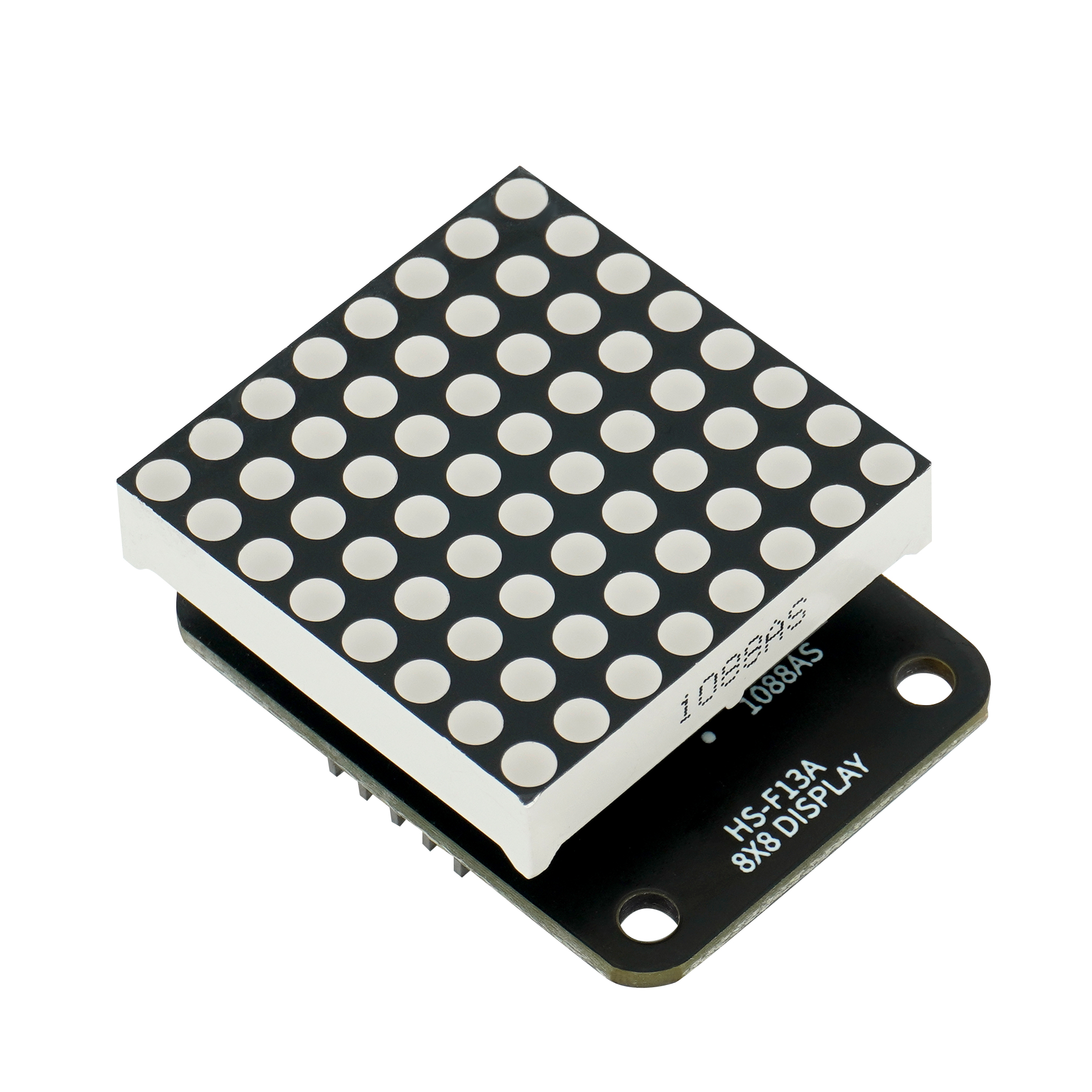
HS-F13A 8x8点阵显示屏
1、介绍 点这里回到目录
8*8 点阵模块由 MAX7219 驱动,MAX7219 是一种集成化的串行输入/输出显示驱动器, 只需要 3个 IO 口即可驱动 1 个点阵,点阵显示时无闪烁且支持级联,8*8 点阵模块通过 Max7219 驱动,Max7219 采用的是三线串行通信,当接收 Arduino 数据时通过芯片内部 8*8 位静态 RAM 储存数据,在通过 Max7219 来控制 8*8 点阵模块的每个引脚的高低电平,从而达到显示目的。
2、原理图 点这里回到目录

3、模块参数 点这里回到目录
| 引脚名称 | 描述 |
|---|---|
| CLK | 时钟引脚 |
| CS | 锁存引脚 |
| DIN | 数据引脚 |
| VCC | VCC(电源输入正极) |
| GND | GND(电源输入负极 |
-
供电电压:3.3V / 5V
-
连接方式:2.54mm排针
-
安装方式:双螺丝固定
4、电路板尺寸 点这里回到目录

5、Arduino IDE示例程序 点这里回到目录
示例程序:点击下载
#include <SPI.h>
#include <Adafruit_GFX.h>
#include <Max72xxPanel.h>

Max72xxPanel myMatrix = Max72xxPanel(9,1,1);
uint8_t  LEDArray[8];

const uint8_t LedArray1[8] PROGMEM ={0x00,0x18,0x24,0x00,0x00,0xa5,0x42,0x00};
const uint8_t LedArray2[8] PROGMEM ={0x00,0x24,0x18,0x00,0x00,0x24,0xc3,0x00};

void setup(){
  myMatrix.setRotation(0,3);
  myMatrix.fillScreen(0);
  myMatrix.write();
}

void loop(){
  //MAX7219上显示笑脸和哭脸各1秒

  memcpy_P(&LEDArray, &LedArray1, 8);
  for(int index_i=0; index_i<8; index_i++)
  {
    for(int index_j=0*8; index_j<0*8+8; index_j++)
    {
      if((LEDArray[index_i]&0x01)>0)
        myMatrix.drawPixel(index_j, 7-index_i,1);
      else
        myMatrix.drawPixel(index_j, 7-index_i,0);
      LEDArray[index_i] = LEDArray[index_i]>>1;
    }
  }
  myMatrix.write();
  delay(1000);
  memcpy_P(&LEDArray, &LedArray2, 8);
  for(int index_i=0; index_i<8; index_i++)
  {
    for(int index_j=0*8; index_j<0*8+8; index_j++)
    {
      if((LEDArray[index_i]&0x01)>0)
        myMatrix.drawPixel(index_j, 7-index_i,1);
      else
        myMatrix.drawPixel(index_j, 7-index_i,0);
      LEDArray[index_i] = LEDArray[index_i]>>1;
    }
  }
  myMatrix.write();
  delay(1000);

}
6、米思齐 Mixly 示例程序(图形化语言) 点这里回到目录
示例程序:点击下载

7、测试环境搭建 点这里回到目录
准备配件:
- CY9599 UNO R3 PRO 开发板 *1
- USB type-c 数据线 *1
- 8X8点阵显示屏(HS-F13A)*1
- 1P母对母杜邦线 *2条 3P母对母杜邦线 *1条
电路接线图:

8、视频教程 点这里回到目录
视频教程:点击查看
9、测试结论 点这里回到目录
器件连接好线之后,将上述程序烧录到 开发板之后,按下复位键,会看到点阵循环显示笑脸和哭脸。